Partition walls on a dry floor: 3 options compared
By Staenis | | Manual
You are renovating a floor and want to combine a dry floor with lightweight partitions. Should the Staenis grid and OSB run across the whole area, or should the walls go in first? Both approaches require a load assessment, but they also create different paths for sound to travel between rooms.
The short answer
To limit the direct connection between rooms through the floor, a sensible starting point is to build the partition on the structural floor first, then install the dry floor separately in each room. Design the junctions to suit the wall and floor systems. A break in the floor alone does not make a room soundproof.
This article concerns lightweight, non-loadbearing internal partitions, such as plasterboard on a metal frame. It is not a construction detail for loadbearing walls or masonry. The diagrams show the principle; board thicknesses, fixings, insulation, seals and floor finishes are not specified.
Three ways to combine the floor and wall
01Continuous floor beneath the wall
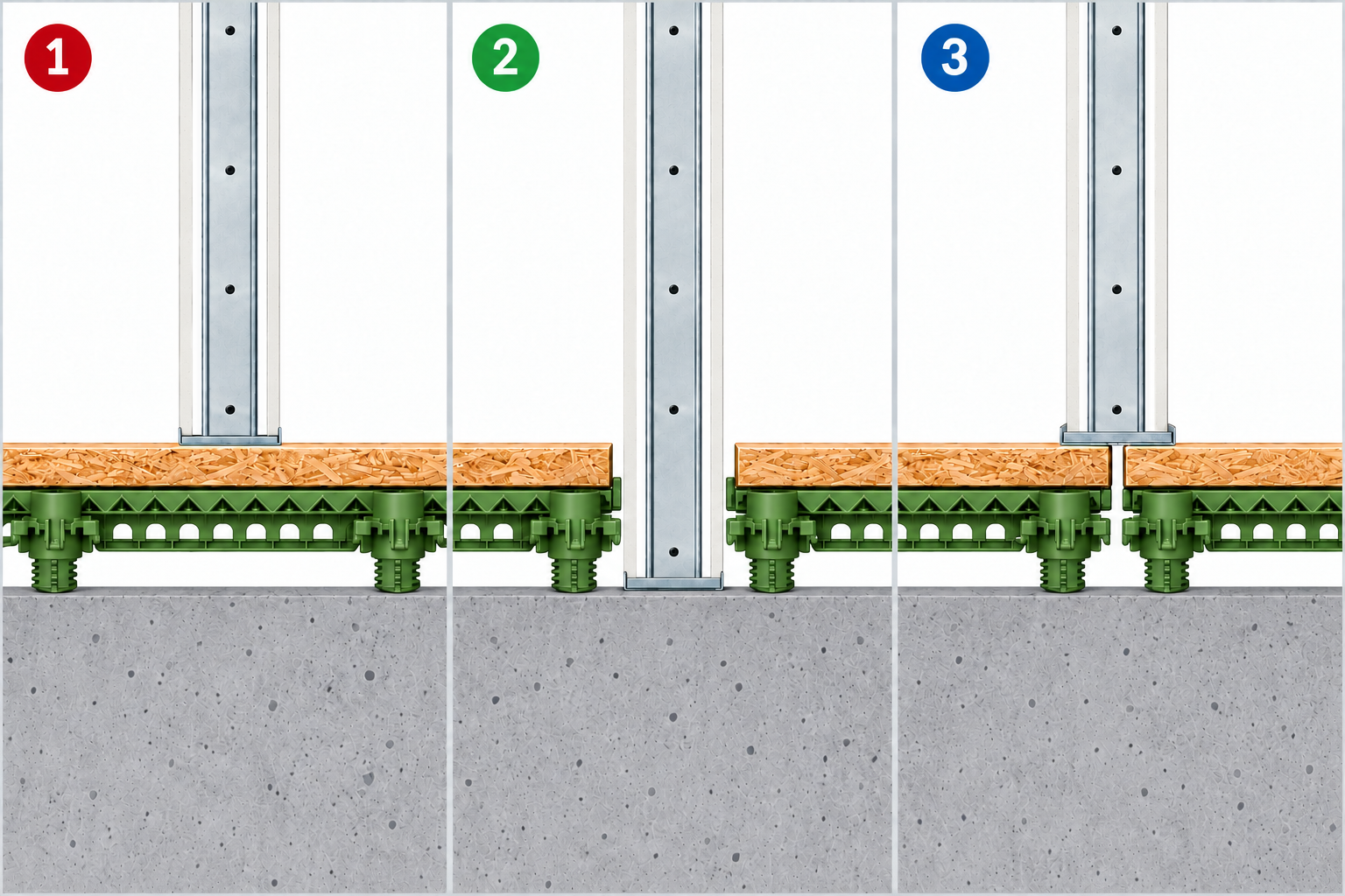
02Wall first, then the floor
03Separate the floor, add the wall later
In the diagram: beige = boards, green = dry-floor grid with adjustable feet, grey at the bottom = concrete structural floor. The wall is a simplified section of a lightweight partition. View the complete schematic
Load capacity and acoustics are separate questions
A load rating for one foot does not, by itself, approve a wall installation. A wall applies a line load. The boards and grid must transfer that load to the supports without excessive deflection, and the existing structural floor must also be able to carry it.
Have the wall weight and height, board build-up, support spacing, door openings and any wall-mounted loads assessed together. Approval for one lightweight partition does not automatically apply to another wall or floor. Timber supports beneath the wall are not automatically a better solution either: their support and connections must also be designed correctly.
1. Run the grid and OSB continuously
With this approach, you build one continuous floor and place the partition on top. This can suit the work sequence, provided the complete build-up is suitable for the wall load. An acoustic connection remains beneath the wall. Footsteps or moving chairs can set the boards and supporting structure vibrating, allowing sound to reach the adjacent room.
Do not choose this option solely because the weight appears acceptable. Consider the acoustic comfort needed between spaces such as a bedroom and a living room.
2. Build the wall on the structural floor first
The wall is installed on the existing structural floor using the junction detail specified for the chosen wall system. The grid and boards are then built separately in each room. This avoids a continuous grid-and-board connection beneath the wall. Of the three principles, this provides the clearest starting point for interrupting that particular sound transmission path.
Sound can still travel through the structural floor, adjoining walls, ceiling, doors or service penetrations. Provide the specified perimeter strips and seals, and avoid rigid bridges at skirtings and finishes. Performance depends on the complete construction, not just the installation sequence.
3. A split floor with the wall above it
Want to install the dry floor first, with the future wall position already fixed? An intermediate detail can be designed. The grid and boards are built room by room with a break beneath the future wall. The board edges need adequate support on both sides. The wall then bears on those supported ends through its bottom track.
A joint of about 1 cm between the OSB sections is one possible project detail, not a universal specification. Coordinate the joint width, edge supports, track width and fixings. With multiple board layers, the intended separation must continue through all relevant layers; a continuous top board reconnects the two sides.
A continuous wall track or its fixings can still connect the two floor sections. This intermediate option is therefore not acoustically equivalent to a wall on the structural floor. Without assessing the complete detail, no specific improvement over option 1 can be promised either.
What should you decide before installation?
- Wall positions and loads: mark walls, doors and heavy wall-mounted items on the plan.
- Floor build-up: specify the boards, supports, finish and junction at each wall.
- Acoustic target: discuss the required comfort and have the full detail assessed where demands are high.
- Junctions: check perimeter joints, skirtings, penetrations and fixings for unintended rigid connections.
The appropriate boards depend on the floor finish and loads. Follow the current dry-floor installation guide for general installation, and have specific wall loads assessed separately. Read the Staenis dry-floor installation guide
Need help planning the wall and floor together?
Send us a plan or sketch showing the wall positions, wall type and weight, existing substrate, available build-up height and intended floor finish. Include which rooms you want to separate acoustically. We can then discuss the installation sequence and the support needed.
Ask about your partition and dry floorFurther reading and technical background
- Buildwise: rigid contacts and acoustic bridges in floors
- Buildwise: acoustic performance of dry-floor systems
These sources explain general acoustic principles. They are not test reports or approvals of the three Staenis junction details shown here.